The SimplIQ Solo Whistle by Elmo Motion Control is a lightweight and highly compact servo drive powered by a DC source, suitable for DC brush and brushless, sinusoidal and trapezoidal motors.
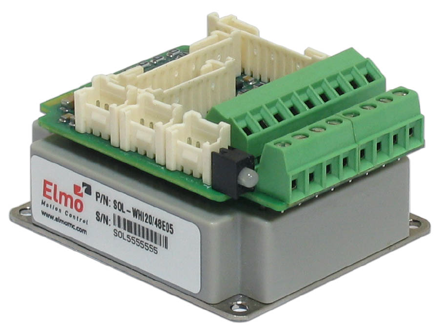
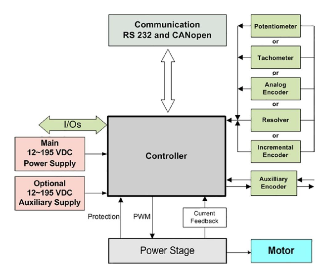
The block diagram below shows the architecture of the servo drive which features a highly configurable controller, RS-232 serial communication and CANopen for fast communication in a multi-axis distributed environment, fault protection, and several feedback options including analog encoder.
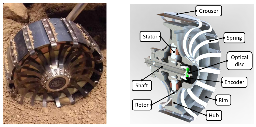
The AMALIA rovers 2.0, 2.1, and 3.0, developed by Team DIANA, employed the SimplIQ Solo Whistle servo drives to control the four in-wheel custom sinusoidal brushless motors featuring 11 pole pairs and an external rotor configuration designed and manufactured by the Technai Team (Marenco, 2014). The two images below show the elastic wheel of the AMALIA rover 2.1 during a test at the ALTEC Mars Terrain Simulator (left) and a CAD cross-sectional rendering highlighting several components, including the optical disc and encoder (right).
During my PhD, I tuned the SimplIQ Solo Whistle servo drive, using the Elmo Application Studio software, as part of the preliminary experimental campaign to assess the tractive performance of the elastic wheel of the AMALIA rover. Later, to test the wheel under higher loads and slip ratios, I replaced the native in-wheel motor with a more powerful Maxon brushless EC 60 motor controlled via the open source VESC platform.
In this post I would like to briefly describe the tuning procedure for the SimplIQ Solo Whistle drive, which I learned while working with Team DIANA, thanks to the guidance of my talented and patient teammates.
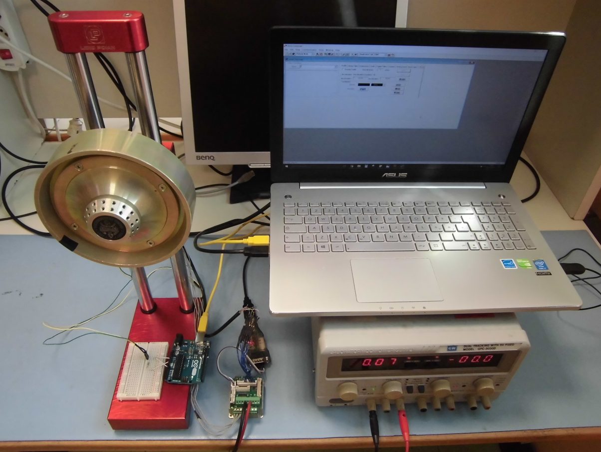
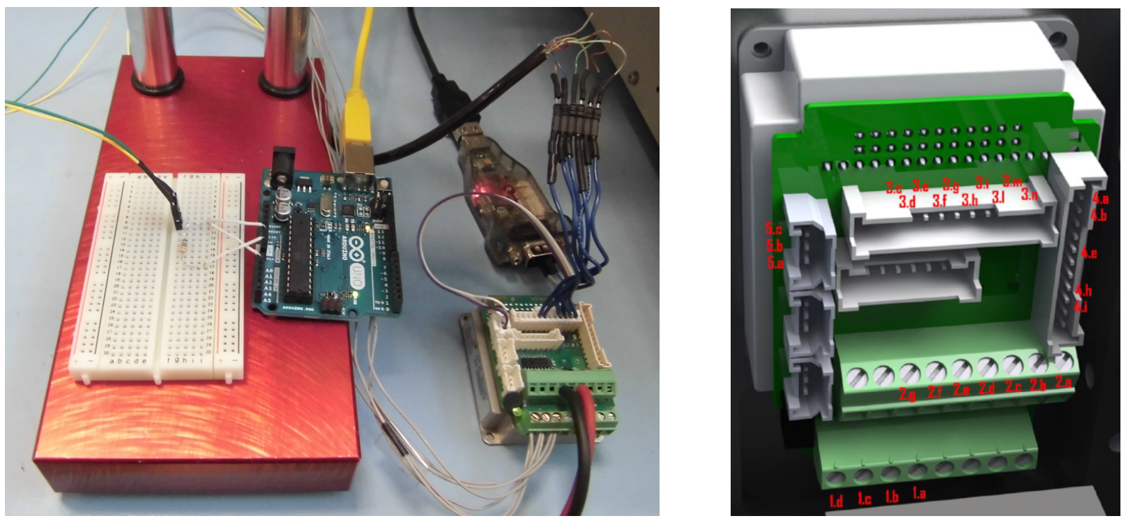
The laboratory setup for tuning the servo drive includes the following components, also displayed in the picture below:
- DC power supply.
- Laptop running the Elmo Application Studio software.
- Wheel rim containing the motor and mounted on a custom-made metal frame.
- Arduino UNO microcontroller board and a solderless breadboard to capture motor temperature data.
- USB-to-RS232 adapter enabling the communication between the servo drive and the laptop.
- Servo drive.
The picture and rendering (Marenco, 2014) below illustrate the wire connections, in particular:
- The three motor phases are connected to pins 1.b, 1.c, and 1.d in arbitrary order, as the tuning software automatically detects the correct sequence.
- The DC power supply is connected via connector 2.
- The encoder is connected via connector 3.
- Serial communication is connected through connector 5: pin 5.a carries the RX signal, 5.b the TX signal, and 5.c the ground
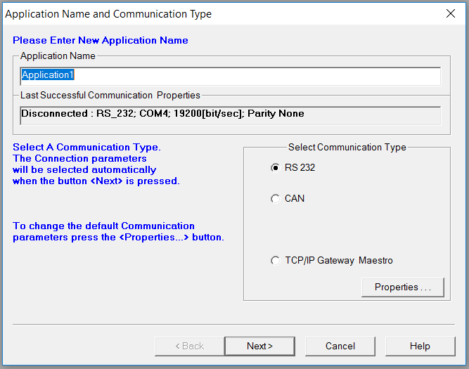
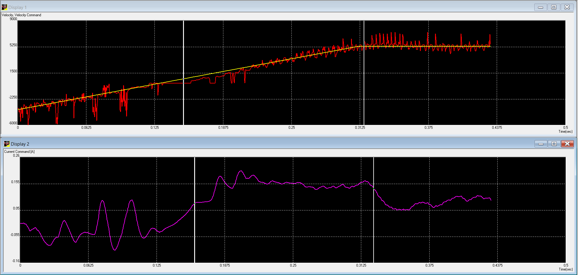
The tuning procedure consists of five main steps: current gain tuning, commutation, digital inputs and outputs, velocity gain tuning and position tuning. The full tuning procedure is presented below through screenshots of the Elmo Application Studio wizard, together with brief descriptions. Moreover, a video of the procedure is available on my YouTube channel; mid-video, whistles and tones are clearly audible as the drive injects test signals to identify resonances.
-
Enter the application name and select the communication type (RS-232).
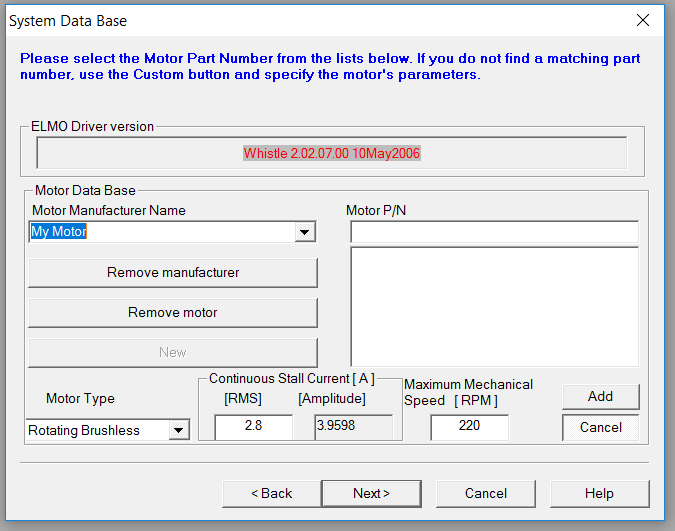
-
Enter the motor name, type and parameters.
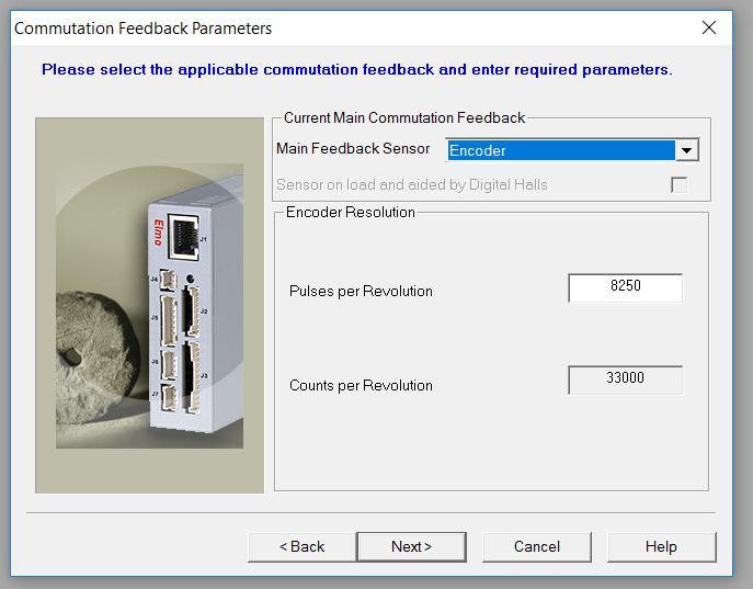
-
Enter the commutation feedback (encoder).
-
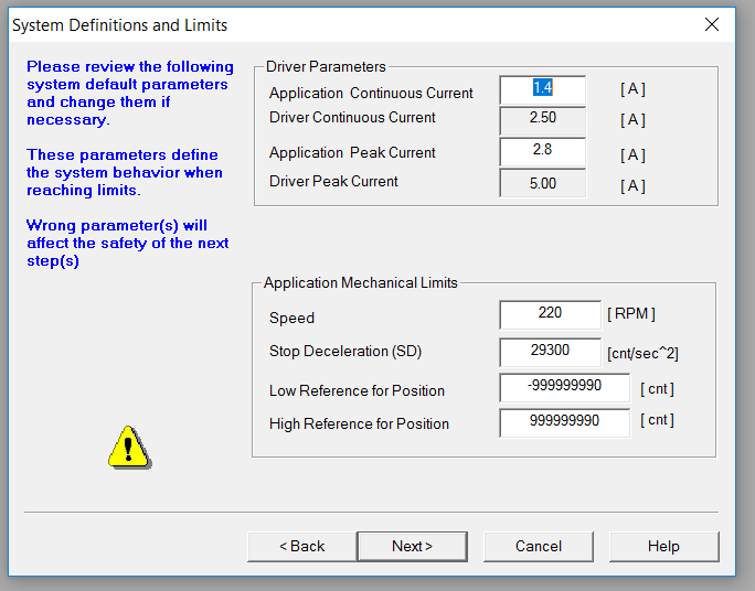
Review/enter the driver parameters.
-
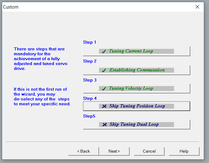
Select the tuning steps to be performed. For this application, the position tuning was not required.
-
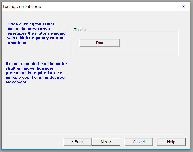
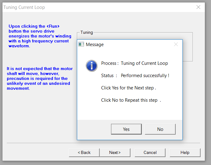
Run the tuning current loop.
-
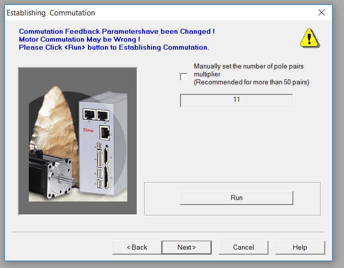
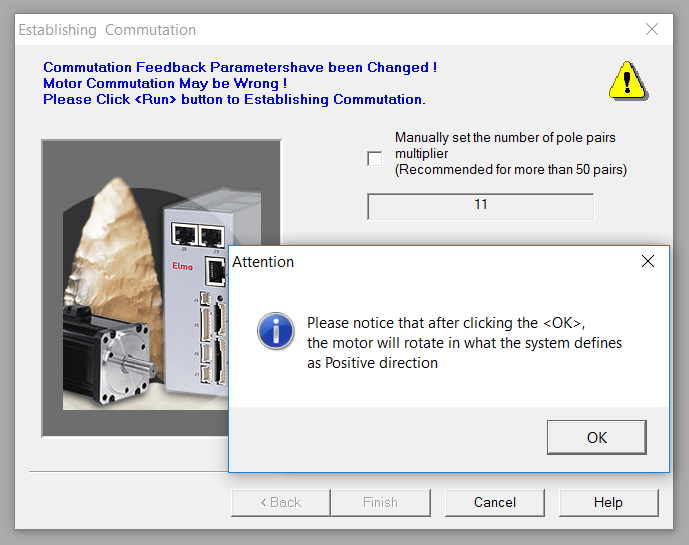
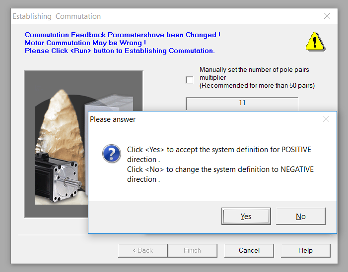
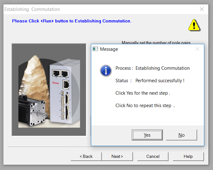
Run the establishing commutation process.
-
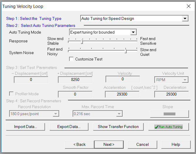
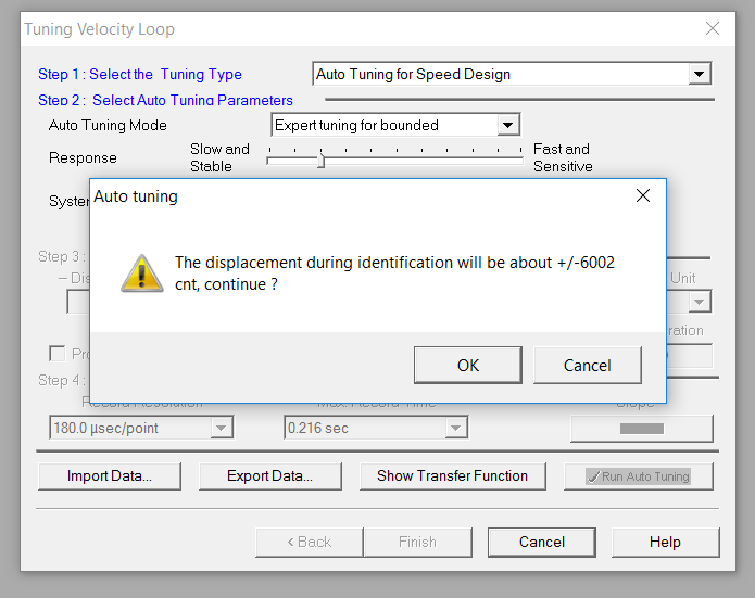
Run the tuning velocity loop. Response is set to Slow and Stable and Noise to Slow and Quiet.
-
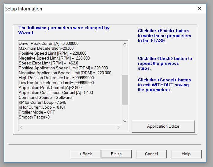
At the end of the tuning procedure a summary of the tuned parameters is displayed.
-
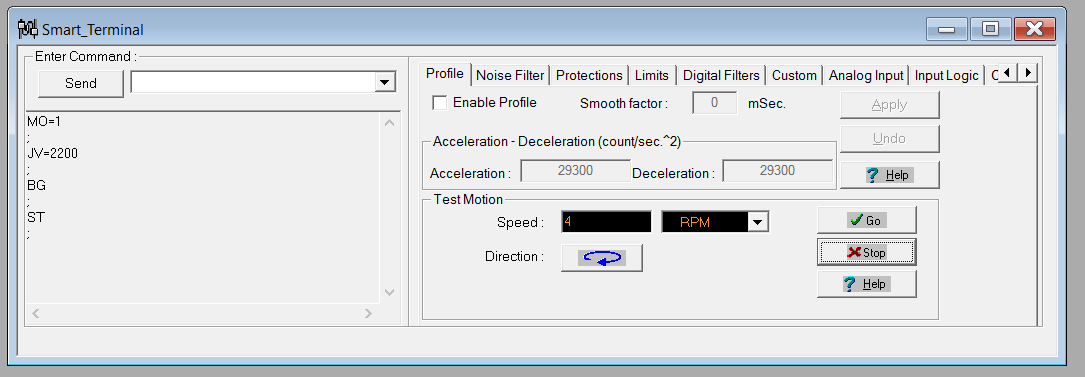
Using the Smart Terminal tool, it is possible to test the tuned servo drive by setting the desired rotational velocity.
During the tuning procedure, some common errors may occur. Below are the most frequent ones and their solutions:
- Can not identify num/dem controller: ensure the encoder wires are securely connected to connector 3.
- Please check the encoder connections: verify the correct wiring order of the encoder.
- Failure – can’t measure motor current: check whether the motor phase wires have come loose.
References
- Marenco, M. (2014). Elettronica di bordo e firmware v3.0 del engineering model del rover per esplorazione lunare D.I.A.N.A. [Master's thesis]. Politecnico di Torino.